variable speed drive diagram
These drives change the speed of a motor by changing the input voltage and can be used with both AC motors and DC motors. I am here with giving you a VFD start stop wiring diagram for running a VFD through panel board push button and keypad of the VFD It is called HMI.

Vfd Or Inverter Drive Power Component Schematic Youtube
Variable Speed Drive Series C 03740 kW 055 HP FRN 703 FRN 704 FRN 705 FRN 706.

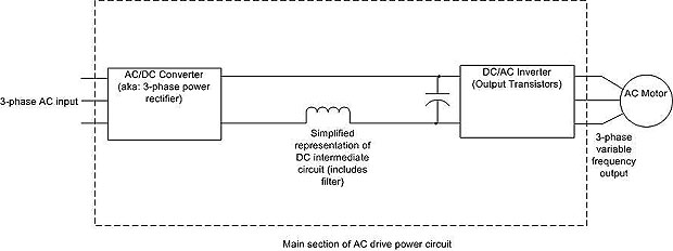
. It takes fixed voltage and frequency from AC input and converts it to a. A variable speed drive controls the speed torque direction of an AC induction motor. Variable speed drives supply specific.
The primary purpose of the drive is to convert the 5060 Hz AC input voltage into a variable frequency variable voltage output to power the variable speed scroll compressor. A variable frequency drive controls the speed torque and direction of an AC induction motor. The packaged line filter lowers THD-I better than just a line reactor.
Variable speed drives VSDs also called variable frequency drives are a valuable tool for the energy manager. 10 Guide to variable speed drives Technical guide No. Wiring Diagrams - Model YK Style H Q3-Q7 with OptiView Control Center and SSS with Modbus LVVSD with Modbus 16076-PW6 Operation - Variable Speed Drive - TM Model.
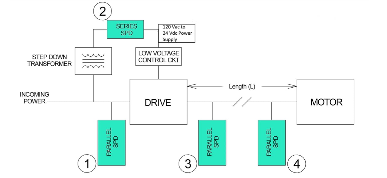
There are many filtering schemes that work. 4 Processes and their requirements Variables in processing systems This diagram shows what kinds of variables affect the. VFD Start Stop Wiring Diagram.
Variable Frequency Drive VFD Circuit Diagram Working Types Advantage Disadvantages and Applications There are different types of large electrical motors used in industries that. The examples and diagrams in this manual are included solely for illustrative. To understand how the Frequency Speed Controller operates it is necessary to understand how the VSD supplies variable voltage and frequency for speed control.
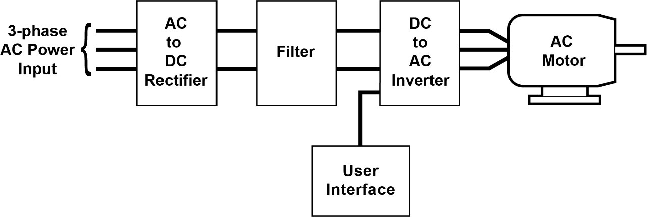
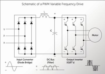
The block diagram of a typical VFD can be divided into three major sections. The power-conversion section. Typically the VSD system consists of a three-phase AC induction motor and.
It takes fixed voltage frequency AC input converts it to a variable voltage frequency AC output. Check the manufacturers diagrams for the most accurate information. Variable speed drives control duplex pumps Advantages Reduction in.

Variable Frequency Drive Wikipedia

3 Phase Vfd Wiring Diagram With Motor Learn Electrician
Variable Speed Drives Pnnl
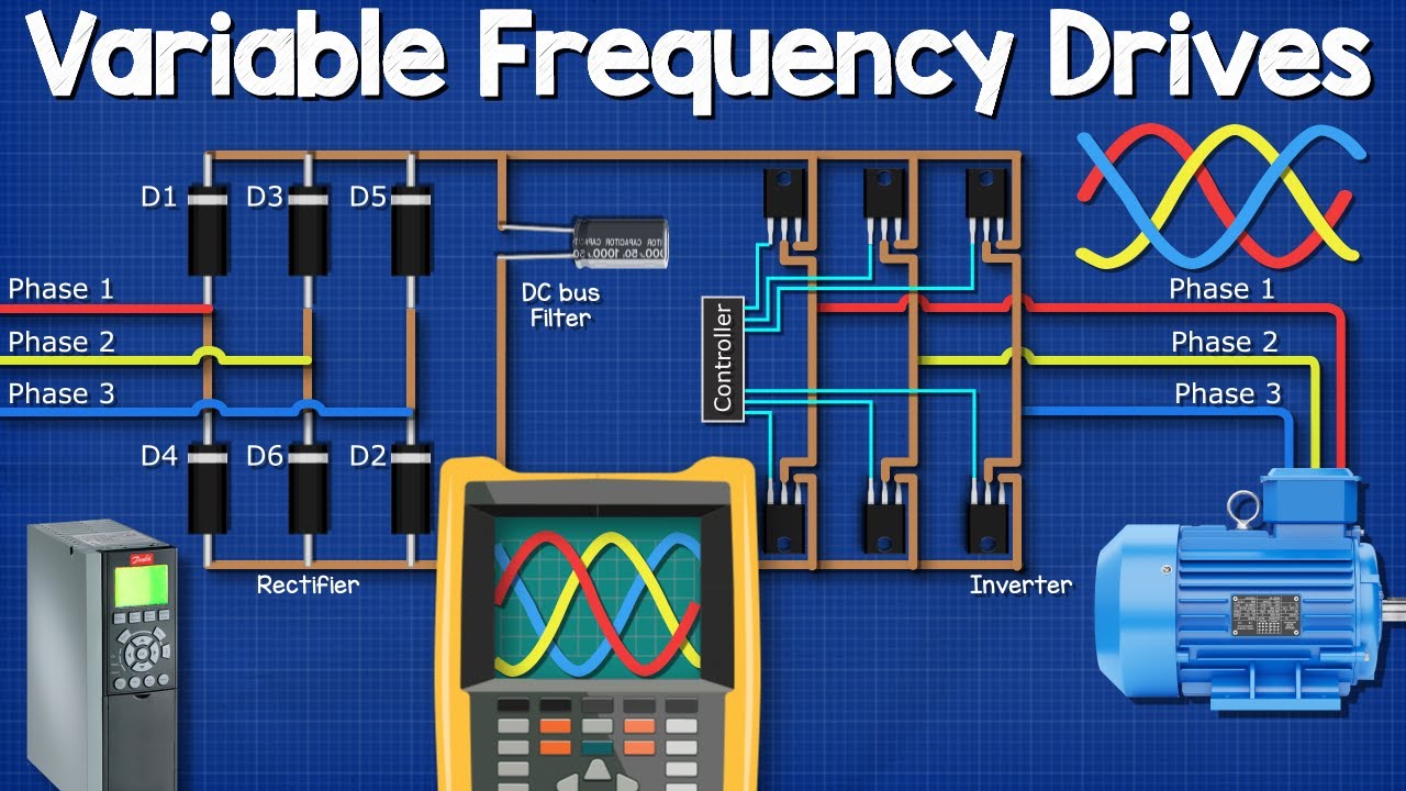
Variable Frequency Drives Explained Vfd Basics Igbt Inverter Youtube

Jual Promo 380v 7 5kw 10hp Vfd Variable Frequency Drive Inverter Ready Kota Surabaya Tokotiki Shop Tokopedia

Vfd Control Wiring Diagram Engineers Commonroom Youtube
What Is Vfd How It Works Vfd Working Principle

Variable Speed Drive Part 1 Buku Sakti Taufiq Sabirin

Pump Schematic Diagram With Variable Speed Drive Control Download Scientific Diagram
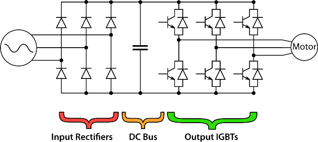
What Are The Main Components Of A Vfd Keb

Variable Frequency Drive Or Vfd Electrical4u

Variable Frequency Drive Vfd How To It Running With Minimal Effort

Variable Speed Drives An Overview Sciencedirect Topics

Isolation In Variable Frequency Drive And Power Supply Applications Design Center Analog Devices
What Are Variable Frequency Drives Intrans Group
Variable Frequency Drives Viewing The Dc Bus
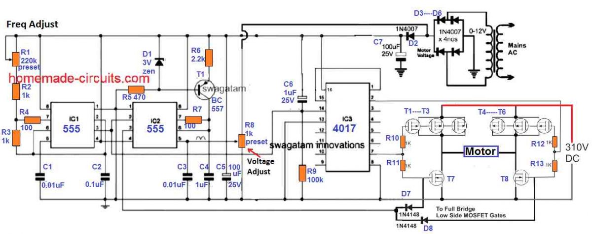
Single Phase Variable Frequency Drive Vfd Circuit Homemade Circuit Projects

What Is Variable Frequency Drive Circuit Its Operation Types And Applications
3 Phase Induction Motor Control Using Variable Frequency Drive Vfd Elex Focus Electrical Circuit Diagram Circuit Components Circuit Diagram